Recommendations for Improving the Life of HD Cartridge Heaters
Tempco Hi-Density Cartridge Heaters have been widely used in many demanding and diverse applications since 1972. The commonly used basic applications are platen, plastic mold and die heating, liquid immersion and air heating.
1. Operating Temperature
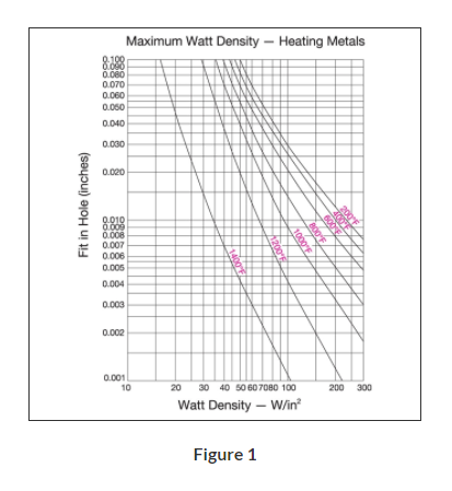
Operating temperature of a heater is a major factor in determining the life expectancy of a heating element. The heater life depends on the actual temperature of the resistance wire within the heater and not on the process operating temperature. The graph in Fig.1 demonstrates the proper relationship between operating temperature and watt density; the higher the operating temperature, the lower the maximum recommended watt density.
2. Heater Watt Density
Cartridge heater watt density is defined as the wattage dissipated per square inch of the heated sheath surface. For a particular application a heater’s watt density governs internal resistance wire temperature, which determines the outer sheath temperature. These factors are critical to the proper heating of the application and to the life expectancy of the heater. Special construction features that promote excellent heat transfer permit Hi-Density Cartridge Heaters to operate at higher watt densities while maintaining the lowest possible resistance wire temperatures of any style cartridge heater.
Heater watt density (w/in2) is calculated using the following formula:
Watt Density =
Heater Wattage
Heated Length × Heater Diameter × 3.1416
Heated length is the overall length of the heater minus any unheated (cold) sections. Standard Type N, Hi-Density cartridge heaters have 3/8″ at the lead end and 1/4″ at the disc end unheated. This would mean a 6″ long heater would have 5-3/8″ effective heated length.
Unheated sections vary with type of heater termination. See Hi-Density Cartridge Heaters for complete details.
The graph in Fig.1 shows the maximum recommended watt density for Hi-Density Cartridge Heaters when used in a steel platen. Watt density limitations for various materials are given in the engineering section of this catalog. For liquid immersion heaters the maximum watt density depends on the type of liquid being heated. The more viscous, or thicker the liquid, the lower the maximum watt density. Higher watt density can cause the liquid to carbonize and accumulate on the heater sheath, which will cause premature heater failure. It is advisable to use heaters that have watt densities below the maximum recommended watt density to get the longest heater life. If the actual heater watt density is close to the maximum recommended watt density, you can correct the problem by:
Increasing the number, diameter and length of heaters.
Lowering the total wattage; however, this may increase the heat-up time.
Obtaining tighter fit (see Fig.2 — Determining Fit).
A Hi-Density cartridge heater designed at the maximum recommended watt density allows the smallest heater to be used to obtain the required wattage with good service life. All things being equal, using a lower watt density heater will typically provide optimized service life.
3. Determining Fit
When heating a platen, mold, die or hot runner probe with Hi-Density Cartridge Heaters inserted into drilled holes, fit is an important factor in determining the life expectancy of the heater. Fit is the difference between the minimum diameter of the cartridge heater and the maximum diameter of the hole. Unheated sections on a Hi-Density cartridge may be smaller in diameter due to swaging. To determine fit, use the smallest diameter on the heated length only.
Example: A 3/8″ nominal OD Hi-Density cartridge heater has an actual diameter of .371″ ±.002, which translates to a minimum diameter of .369″. If used in a .376″ ±.002 hole, the fit would be .009″ (.378″ − .369″ = .009″).
When medium watt density heaters (less than 60 watts per square inch) are used in low temperature applications (less than 600°F [315°C]) general purpose drills are commonly used to drill holes. The typical hole size may be .003″ to .008″ over the drill size. For higher watt density and/or higher temperature applications, we recommend that the holes are drilled and reamed for the tightest possible fit. In applications where precise temperature control and heat transfer properties are required, Hi-Density cartridge heaters can be centerless ground to ±.0005″.
Although a tighter fit is desirable to efficiently transfer heat and to get long heater life, a looser fit will aid in installing and removing heaters, especially long heaters. We recommend that you apply Tempco’s BNS anti-seize cartridge heater coating as it will improve heat transfer and will make the removal of heaters easier.
The graph in Fig 1. (above) shows the effect of fit in determining the maximum recommended watt density on a steel platen. As it is indicated in the graph, the tighter the fit, the higher the maximum recommended watt density.
4. Temperature Control and Location of Temperature Sensing Device
In order to better control the heater temperature and hence the resistance wire temperature, use of an appropriate temperature control and the proximity of the heater to the sensor is very important. The graph in Fig. 1 (above) shows the effect of operating temperature in determining the maximum recommended watt density on a steel platen where the sensor is located 1/2″ from the heater. Higher watt density heaters can generate heat faster than the surrounding area’s ability to dissipate heat. This creates a thermal lag between the heater and the sensor. The closer the sensor to the heater, the better you can control the heater temperature. By keeping the sensor further from the heater, temperature gradients of several hundred degrees can be observed in many applications, especially during initial start-up and heavy thermal cycling. Although the set operating temperature may be low, the heater may be running at a very high temperature. This is a common cause of heater failure. This can be minimized using time proportional and PID functions of the temperature controllers.
5. Power Control
Power control methods affect the life expectancy of heating elements. In general, although economical, on-off controls increase thermal fatigue and oxidation rate on heating elements by causing wide temperature swings of the internal heating element. Silicon Controlled Rectifiers (SCR’s), Mercury Relays and Solid State Power Controls can increase the life expectancy of heating elements by reducing the temperature swings of the internal heating element.
We use cookies to optimize our website and our service.
Functional
Always active
The technical storage or access is strictly necessary for the legitimate purpose of enabling the use of a specific service explicitly requested by the subscriber or user, or for the sole purpose of carrying out the transmission of a communication over an electronic communications network.
Preferences
The technical storage or access is necessary for the legitimate purpose of storing preferences that are not requested by the subscriber or user.
Statistics
The technical storage or access that is used exclusively for statistical purposes.The technical storage or access that is used exclusively for anonymous statistical purposes. Without a subpoena, voluntary compliance on the part of your Internet Service Provider, or additional records from a third party, information stored or retrieved for this purpose alone cannot usually be used to identify you.
Marketing
The technical storage or access is required to create user profiles to send advertising, or to track the user on a website or across several websites for similar marketing purposes.