RTD’s
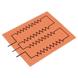
The RTDs (2- or 3-wire) used are platinum thin film 100 ohm @ 100°C. The standard curve is 0.00385 TCR / DIN432760. Other common RTDs such as 1000 ohm can also be used. Specify when ordering.
The RTD’s resistance increases with a rise in temperature and is considered the most accurate and stable sensor.
Thermistors
Thermistors are also a resistive-based temperature sensor. They do not generally respond in a linear style and are used in a limited temperature range or at a specific single temperature.
Small bead style thermistors can be mounted directly on the heater.
The thermistor’s response is generally designed directly into the customer’s electronic control system. Therefore if a thermistor is required, specify manufacturer, specific model number, type and specifications when requesting a quote. Consult Tempco for more information.
No Temperature Sensor
A temperature sensor is not needed for this heater.
Additional Options
Internal Ground Screen Plane
Some applications may require the heater to be grounded. Due to the fact that the heater sheath is non-conductive, this can only be done artificially. A second layer of insulating material and a conductive grid can be added to the heater. A ground wire is attached to the grid.
A less expensive alternative for setting up a ground wire, especially for the required ground lead of a cordset, is to have a “flying ground lead” (6″ long, green) exit the lead patch for attaching to the metal load surface, effectively grounding the process.
Dual Voltage/3-Phase
Due to the flexibility in circuit design for flexible heaters, heating circuits can be designed to accommodate dual voltage.
On dual voltage heaters, three leads, including a common in a different color, are provided for wiring the heater in series for the higher voltage and parallel for the lower voltage. 120/240 Vac or 240/480 Vac can be specified.
Three-phase circuits can also be designed for large high-current applications.
Self-Limiting/Self-Regulating
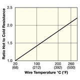
The alloy used for this heater’s resistance wire has a high positive temperature coefficient of resistance that allows the heater to reduce power as temperature increases. This self-regulating feature is ideal for many low temperature applications. This feature can also be beneficial when a fast start-up time is required before the heater power levels off to normal
operating temperature.
See Chart for Ratio of Hot to Cold Resistance of the Heater wire at various wire temperatures.
Thermal Sponge Insulation / Thermal Conductive Sponge
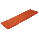
To increase heater efficiency, silicone sponge rubber insulation can be bonded to the top side of the heater.
Available thicknesses are 1/16″, 1/8″, 1/4″, 3/8″ or 1/2″.
Thermal Conductive Sponge can be use to transfer heat evenly to various surfaces. Available in 1/8″ thickness.
Foil Backing
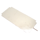
Aluminum foil can be added to the back of the heater to help dissipate the heat between element runs and eliminate hot spots. Due to the foil, higher watt densities and better temperature uniformity can be attained. The foil would be applied to the back of the heater, on the mounting surface.
Holes and Cutouts
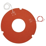
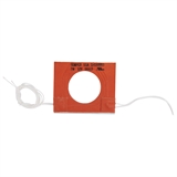
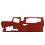
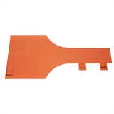
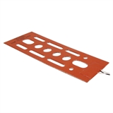
Holes and cutouts in the surface of a silicone rubber heater can generally be placed anywhere in the heater assembly. Holes and cutouts can be used to allow space for bolts, nuts, temperature sensors, brackets, etc. For most holes and cutouts, a detailed drawing will be required for quoting or ordering.

