
![]()
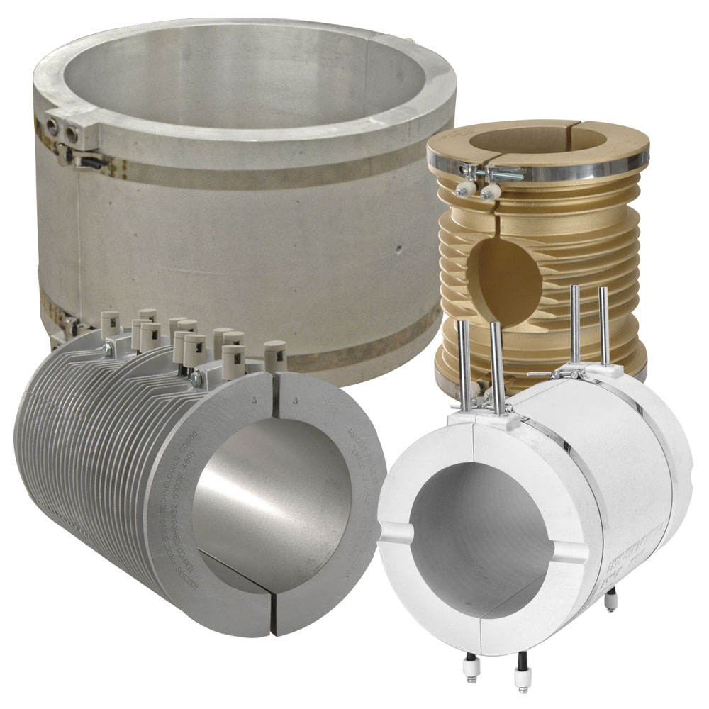
As a standard, Cast-In Band Heaters are manufactured in aluminum alloys because this material provides very good thermal conductive properties. For applications requiring higher operating temperatures and/or higher watt densities, bronze or brass alloys can be used.
- About

- Clamping Options
- Electrical Terminations
- Terminal Protection
- Cooling/Flow Tube Fittings
- Installation Accessories

Cast Materials

Aluminum
Material: Standard Aluminum 319 (Optional Aluminum 356 in Learn More)
Maximum Surface Temperature: 700°F (371°C)
Density (lb/in3): 0.101
Coefficient of Linear Thermal Expansion (in/in/°F × 10-6): 12.7 @ 68° – 572°F
Thermal Conductivity (BTU-in/hr-ft2-°F): 754

Bronze
Material: Bronze
Maximum Surface Temperature: 1350°F (732°C)
Density (lb/in3): 0.272
Coefficient of Linear Thermal Expansion (in/in/°F × 10-6): 9 @ 68° – 572°F
Thermal Conductivity (BTU-in/hr-ft2-°F): 437

Brass
Material: Yellow Brass
Maximum Surface Temperature: 1200°F (649°C)
Density (lb/in3): 0.304
Coefficient of Linear Thermal Expansion (in/in/°F × 10-6): 12.2 @68° – 500°F
Thermal Conductivity (BTU-in/hr-ft2-°F): 582
Cooling Methods
None
This cast-in does not need a cooling feature.

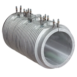
Finned without Side Flanges
The standard mounting method for these designs is bolt clamping. An alternative mounting method is to use stainless steel straps. Type “T” screw terminals are the standard termination.

Finned with Side Flanges
The standard mounting method for these designs is bolt clamping. An alternative mounting method is to use stainless steel straps. Type “E” screw terminals are the standard termination.

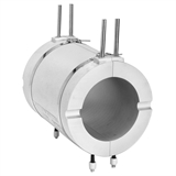
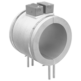
Liquid Cooled Band – Single Set of Cooling Tubes
The single set cooling tube design features 1/4″, 3/8″ or 1/2″ diameter tubing precisely formed into a serpentine or any other suitable shape and cast into the body of the Cast-In Heater. This is the most widely used method for providing a means of cooling in liquid-cooled Cast-In Heaters. From this basic design, the user can choose to factory equip the cooling tubes with any of the cooling tube termination options.

Liquid Cooled Band – Dual Set of Cooling Tubes
The Dual cooling tube design incorporates two sets of 3/8″ or 1/2″ diameter tubing formed into a serpentine or any other suitable shape within the same Cast-In Heater. Dual cooling tubes will actually double the operating life of a Cast-In Heater with liquid-cool function, since cooling tube failures usually occur before heating element failures

Liquid Cooled Band with Recessed NPT Fittings
The recessed cooling tube design incorporates 3/8″ or 1/2″ diameter tubing formed into a serpentine or any other suitable shape with specially designed stainless steel NPT fittings that are welded to the tube ends and cast below the surface of the Cast-In Heater, thus eliminating the troublesome, commonly used tube extensions as they exit the casting for connection to the coolant lines.
Clamping Options
Strap Clamping
Strap clamping is used to secure the heater to the extruder barrel with 3/4″ or 1-1/4″ wide low expansion stainless steel clamping straps with 1/4″-20 socket head cap screws and barrel nuts.

Bolt Clamp
Strap clamping is used to secure the heater to the barrel by bolts clamping the two halves together around the barrel. A variety of bolt clamping designs and hardware is available.
Electrical Terminations
None
This cast-in will not have an electrical termination. It is for cooling only.

Type S: Heavy Duty Ceramic Insulators (Standard)
Standard unless otherwise specified.
.315″ diameter heater has 8-32 screw terminals.
.430″ diameter heater has 10-32 screw terminals.

Type T: Mica Insulator
Mica insulator is the same diameter as the heating element.
.260″ diameter heater has 6-32 screw terminals.
.315″ diameter heater has 8-32 screw terminals.
.430″ diameter heater has 10-32 screw terminals.
Type T7: Ceramic Insulator
Ceramic insulator is the same diameter as the heating element.
.260″ diameter heater has 6-32 screw terminals.
.315″ diameter heater has 8-32 screw terminals.
.430″ diameter heater has 10-32 screw terminals

Type C4: Heavy Duty Ceramic Insulator with Terminal Cover
Heavy duty ceramic insulator with terminal cover.
.315″ diameter heater has 10-32 screw terminals.
.430″ diameter heater has 10-32 screw terminals.

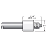
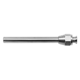
Type P: Plain Pin
Plain terminal pin. Specify Length “L.”
Standard 1/2″ (12.7 mm) pin length.

Type R: Mica Washers
Mica washers with 90° blockhead screw terminal with 10-32 screw threads.
Available for .315″ and .430″ diameter heaters.

Type R2: Mica Washers with Lead Wire Connection
Mica washers with blockhead and through hole for lead wire connection. Eliminates the use of ring terminals.
Available for .315″ and .430″ diameter heaters.
Accepts 6-14 gauge wire.

Type E: Right-Angle Lug
Right-angle lug welded to pin with mica washer insulators and 10-32 binding head screw.
Available for .260″, .315″ and .430″ diameter heaters.

Type L and L9: Terminal Lug and Pin
Terminal lug spot welded to pin with 10-32 binding head screw.
Available for .260″, .315″ and .430″ diameter heaters.
Type L represents straight; Type L9 represents 90° to pin. Specify lug orientation.

Type SF and SF9: Quick Disconnect Spade Tabs
Quick-disconnect spade tabs spot welded to pin.
Available for .260″, .315″ and .430″ diameter heaters.
Type SF represents straight. Type SF9 represents 90° to pin. Specify tab orientation.

Type F: Flexible Lead
Flexible lead: insulated stranded wire crimped to cold pin. Crimp connection is insulated with fiberglass sleeving.
Available for .260″, .315″ and .430″ diameter heaters.
Wire insulation rated to 250°C, 450°C optional. Specify lead length.

Type R1: Flexible Armor Cable
Flexible Armor Cable provides excellent protection to lead wires against abrasion and contaminants.
Available for .260″, .315″ and .430″ diameter heaters. Specify cable length and lead length. Style may vary from depiction depending on heater diameter and cable diameter used.

Type R1A: Stainless Steel Wire Overbraid
Stainless Steel Wire Overbraid provides flexibility and excellent protection to lead wires against abrasion.
Available for .260″, .315″ and .430″ diameter heaters. Specify stainless steel wire overbraid length and lead length.
Style may vary from depiction depending on heater diameter and braid diameter used.

Type MR: Strain Relief and Lead Wire – Moisture Resistant
Moisture resistant shrink strain relief and lead wire with or without stainless steel overbraid.
Available for .260″, .315″ and .430″ diameter heaters. Specify lead wire and overbraid length.
Maximum operating temperature is 350°F (177°C).

Type TS: Teflon® Sleeving over Lead Wire
Contamination seal shrink-down Teflon® sleeving over the heater and lead wire splice. Provides a good moisture resistant seal. Maximum operating temperature 500°F (260°C).
Available for .260″, .315″ and .430″ and diameter heaters. Specify lead length.
Termination Protection

Type C2: Standard Terminal Box (on flat pad)
Type C2 is an individual terminal box for protecting the terminals on each Cast-In Band Heater half and on many other Cast-In Heater designs with one set of heater terminals.
The C2 box design requires a flat pad on half-round castings or a flat surface on other casting designs for mounting. It is made from heavy gauge, rust-resistant sheet metal. The cover is removable for easy access to terminals. The box has two 7/8″ diameter knockouts opposite each other for standard 1/2″ BX connectors.

Type C7: Terminal Box attached to Clamping Straps
Type C7 terminal boxes are made from rust-resistant sheet metal. The C7 base is fixed to the clamping straps. The box has two 7/8″ diameter knockouts opposite each other for standard 1/2″ BX connectors. The cover is removable, providing easy access to the screw terminals for electrical wiring.

Type P2: Quick Disconnect Plug Assembly with Box
Quick-Disconnect Cup assemblies provide the simplest and safest means for applying power to any type of Cast-In Heater installation. The box extends over the screw terminals on both Cast-In Band Heater halves. The combination of prewired cup and box assembly, along with factory prewired high temperature lead wire protected with armor cable, eliminates live exposed heater terminals and electrical wiring, protecting employees from electrical shock and the possibility of electrical shorts due to exposed wiring.

Type EP: Explosion & Moisture Resistant Box
Cast iron explosion and moisture resistant boxes should be used in areas where the surrounding air may become contaminated with combustible gases or a high humidity level may exist. Installation requires one box per Cast-In Heater half and they are brazed to the tubular heater. The standard box has one 1/2″ NPT hub.

Type MPR: Moisture Resistant Box
This design has a moisture resistant die cast aluminum box with a non-removable polyurethane gasket in the lid. Lid is secured with captive stainless steel screws. Body and lid are painted in basic industrial gray; interior contains copper ground screw. Box is mounted to a plate that is brazed to the element. Available in a wide variety of sizes.

Type MR1: Moisture Resistant Box with Shield
This design incorporates the MPR housing style along with a perforated tube shielding unheated extensions of the tubular heating elements. This feature provides mechanical strength to the element extension and prevents overheating of the terminals, reducing possible premature failure from corrosion and oxidation.

Type CB: Cast Aluminum Box
A Cast Aluminum Box is used to protect and secure lead wire terminations on narrower designs.
None
This Cast-In will not have Terminal Protection.
Cooling/Flow Tube Fittings

Type FF: Flared Seal Fittings
Brass flared seal fittings are well adapted for low to medium
pressure and resistant to mechanical pullout. Available for 3/8″ and 1/2″ diameter tubing with SAE 45° flare.
| Diameter Tubing |
Thread | Part Number |
|---|---|---|
| 3/8″ | 5/8″-18 | FTG-124-101 |
| 1/2″ | 3/4″-16 | FTG-124-104 |

Type HS: Hi-Seal Fittings
Hi-seal brass fittings are highly dependable under the most adverse conditions. For reliable and trouble-free service with ease of installation, we strongly recommend hi-seal fittings.
Available for 3/8″ and 1/2″ diameter tubing. Male thread is 1/2″ NPT for 1/2″ tube and 3/8″ tube.
| Diameter Tubing |
Part Number |
|---|---|
| 3/8″ | FTG-118-124 |
| 1/2″ | FTG-118-116 |

Type RA: 90° Copper Elbow
90° copper elbow is brazed to the Cast-In Heater cooling tube extension with additional tube extension for connecting cooling lines with compression and/or flared fittings.
Available for 3/8″ and 1/2″ diameter tubing. If required, specify.
| Diameter Tubing |
Part Number |
|---|---|
| 3/8″ | FTG-127-102 |
| 1/2″ | FTG-127-103 |

Type RT: Cast Brass 90° Elbow
90° threaded elbow is brazed to the cooling tube extension,
providing an easy and quick method for connecting cooling lines. Recommended to be factory installed to assure good braze seals.
Available for 3/8″ and 1/2″ NPT internal threads. If required, specify.
| Diameter Tubing |
NPT | Part Number |
|---|---|---|
| 1/2″ | 3/8″ | FTG-125-101 |
| 1/2″ | 1/2″ | FTG-125-102 |

Type R3: Straight Threaded Copper Fitting
Straight threaded fitting is brazed to the cooling tube extensions, providing an easy and quick method for connecting cooling lines. Recommended to be factory installed to assure good braze seals.
Available for 3/8″ and 1/2″ diameter tubing with internal threads. If required, specify.
| Diameter Tubing |
NPT | Part Number |
|---|---|---|
| 3/8″ | 3/8″ | FTG-131-103 |
| 1/2″ | 3/8″ | FTG-131-102 |
| 1/2″ | 1/2′ | FTG-131-101 |
Installation Accessories

Tubing for Cooling Lines
Cooling Line Tubing can be used to connect the Tempco Cast-In heat/cool bands to the plumbing system of your extruder. Tubing is available in 6’8″ lengths for U.P.S. shipments and up to 20′ lengths for truck shipments. Barlow’s formula below was used to calculate Working Pressure in the table.

Wire Braided Hose
Flexible Teflon® Wire Braided Hose provides an excellent means of connecting Cast-In Heaters to the extruder plumbing system. This style of hose meets the demands of medium to tight bending radius requirements. The stainless steel braid protects the Teflon® hose from any harsh mechanical conditions that may be present.

Adaptor Fittings
Rigid brass adapter fittings are used to mate the base hose assembly to your existing installation.
Additional Options
125 RMS Standard
RMS Surface Finish as defined in ASME B46.1 — RMS is the root mean square of the profile height deviations from the mean line, recorded within the evaluation length. The standard surface finish for the machined surface of Tempco cast-in heaters is 125 RMS. Consult Tempco if a different surface finish is required.
Special Features
Electroless Nickel-Plated — A plating technique (without using an electric current) used to deposit a coating of nickel on a substrate to prevent corrosion, wear and also as a protective coating.
Teflon Coating — Teflon is non-reactive so it is often used in containers and pipework for reactive and corrosive chemicals.
Hard coat anodizing — Anodizing increases resistance to corrosion and wear.
Magnaplate — Strong wear and corrosion resistance non-stick coating that withstands high temperatures.